Part I
copyright 2008 R. A. Suomala
Fifty plus years ago I was working on the development of a closed circuit television system for high altitude aerial reconnaissance meant to be used in the North American A3J, Vigilante, aircraft.
I was at the time employed by The Radio Corporation of America (RCA) as it was then known. RCA's task was to develop the video camera and monitor (Both employing transistors in this type of application for the first time!) while Eastman Kodak was responsible for the optical design. We needed an accurate means to measure both the camera sensitivity and the "brightness" of the monitor screen. RCA had some of the best brains in the business then including Otto Schade, the inventor of the modulation transfer function (MTF) method of measuring resolution in optical systems. When consulted regarding the measurement of luminance (see note 1), Schade recommended the SEI Exposure Photometer made by Salford Electrical Instruments in the UK. This device was the "gold standard" for making field measurements of luminance at the time. With its 1/2 degree measuring spot and a range from 0.0032 to 3200 candles per square foot there is almost no luminance level that can not be measured with the SEI photometer.
During that time the SEI Exposure Meter was a common sight on Hollywood movie sets for exposure measurements and in theaters to measure the on screen luminance of a projected image of an open film gate so that moviegoers would a perceive a standard image "brightness".
As an exposure meter for still photography the SEI does not measure in the way of other meters that simply measure the light incident on the subject or the reflected ambient light from a middle gray card or a fairly large area of the reflected light from the overall image. Instead the SEI measures, in the case of negative film, the exposure required to capture detail in the darkest spot and, in the case of reversal (positive) film, the exposure required to capture detail in the brightest spot. This provides a sort of a built in zone system, but not for exposures based on the reflected light from a 12-18% gray card. However if one wishes to make this type of reading, it can be made if a +3-1/2 stop correction is made from the negative film reading.
The SEI works on the Bunsen grease spot photometer principle (the what? you say). It seems that among other things invented by Robert Bunsen (1811-1899) was the Bunsen grease spot comparison photometer. And of course this is the same Bunsen who invented the Bunsen burner we old guys used in chemistry class (do they still allow this?). The Bunsen photometer was used to compare the intensities of two light sources in an otherwise darkened room. It is just a vertical piece of brown wrapping paper with a greasy spot on it and a light source on each side. When the light on the far side is brighter than the near side light, the grease spot looks lighter than the surrounding paper. When the light on the far side is less bright, the spot appears darker than the surrounding paper, but if the light projected from the both sources is equal, the spot disappears altogether. By the way, Bunsen also invented the carbon-zinc dry cell battery that is used to power the lamp in the SEI photometer.
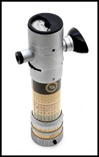
Using the SEI the operator looks through the small 1.3 X telescope and places the centrally located 1/2 degree spot on the area where the luminance is to be measured. The internal lamp is turned on and the base of the instrument is rotated until the spot disappears. Exposure or luminance readings are taken from the barrel of the instrument. An index mark (screw head) on the base of the instrument indicates actual luminance in candles per square foot.
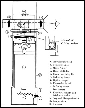
Sounds simple? Not really, as you can see from the schematic diagram below. The luminance of the internal lamp is adjusted using the rheostat (N) until the electrical output of the photoelectric cell (H) matches the calibration mark on the microammeter (A). Turning the base of the instrument drives the two neutral density optical wedges to vary the luminance of the upper diffusion screen (F) image reflected by the mirror spot (C).
Noticing an SEI photometer on the table for $25 at a recent WPHS meeting, obviously I just had to have it. Besides, how else can the WPHS do its good work (i.e. scholarships, etc.) if no one buys.
The SEI photometer is a beautiful piece of craftsmanship. All of its components are of the highest quality. The only way to really destroy it would be to throw it up against a concrete wall or leave the size D dry cell inside until it leaks. Fortunately this one was as clean as a whistle inside and bore no scars outside.
The next installment of this article will discuss how the SEI was put back into service.
Note 1: Brightness is a subjective attribute of light to which humans assign a label between very dim and very bright (brilliant). Brightness is perceived, not measured. Luminance is the measurable quantity which most closely corresponds to brightness.
The following Internet pages were used for reference:
www.shutterbug.net/techniques/lighting/1002sb_thesei/
www.photomemorabilia.co.uk/Ilford/Exposure_Meters.html
www.huws.org.uk/
www.kcbx.net/~mhd/2photo/film/expose/sei.htm
www.rogerandfrances.com/photoschool/sei.html
www.crompton.com/wa3dsp/light/lumin.html
http://photo.net/bboard/q-and-a-fetch-msg?msg_id=001F8z
Part II
copyright 2008 R. A. Suomala

The SEI photometer described in the first part of this article while not completely dead was never the less unable to make accurate measurements since with the lamp at maximum output the pointer on the microammeter was barely on scale and could not be set to the "standard brightness" calibration mark.
The common failure modes for an SEI photometer that has not suffered from corrosion due to a leaking battery are: 1. Lamp burned out (see note 1), 2. Microammeter dead, 3. Photocell dead or output low.
The lamp checked out OK. The only obvious problem with the microammeter was a slight out of balance condition of the movement. This was later corrected by successively applying very small amounts of aluminum filled epoxy to the balancing arm until the zero reading became consistent in all orientations of the meter.
By process of elimination it was clear that the output of the photocell was low. I contacted Megatron1 in the UK and they were able to supply a replacement selenium photocell.
The new photocell had a higher output than the original one did when new, so it was necessary to install a miniature potentiometer in series with the original calibration resistor (I don't feel that this in any way compromises the integrity of the restoration because if the original designers had access to these miniature potentiometers common sense would have dictated their use instead of custom fixed value resistors) (See Note 2).
The potentiometer used is a 5000 ohm, Bourns model 3266 with side adjustment screw (See note 3). The model 3266 is approximately 0.27 inches square by 0.18 inches thick. The temperature coefficient is 100 parts per million per degree centigrade which is adequate for this application. The potentiometer was attached to the meter's permanent magnet using an adhesive sold under the brand name "Plastic Surgery". This stuff will adhere to almost any plastic as well as metals. You will note that the soldering work is not pretty but it is as functional as any done by a NASA certified technician.
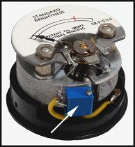
The sidewall of the microammeter cover had to be modified by cutting out a small section to provide clearance for the potentiometer and associated wiring.
Now the light from the lamp can be adjusted so that the output of the photocell can reach the "Standard Brightness" calibration mark on the microammeter.
Using the exposure meter in a DSLR (digital single lens reflex camera) and a white screen on a computer display to calibrate the SEI within practical accuracy seemed to be one way to avoid the need for an expensive calibrated standard light source.
Calibration of hand held reflected light exposure meters and the metering systems in cameras is complicated by the mysterious "K" factor which really came about because of a mixing of English and SI units (the modern form of metric units- International System of Units, abbreviated SI from the French Le Système International d'Unités). The conversion factor for square feet to square meters is 10.76 (1 meter = 39.37 inches, 1 foot = 12 inches, 39.372 / 122 = 10.76) but this led to under exposed negatives. So most manufacturers now use the ANSI/ISO 2720-1974 recommended arbitrary of value of 12.5 for K applied to the luminance in candles per square meter to place a medium gray tone somewhere near the middle dynamic range of the film or sensor, in the case of a digital camera. This is further effected by the use of 11.4 for K prior to 1971. Minolta (now Kenko) and Pentax tended to use a K of 14 (See note 4).
Luminance is the measure of the ambient light reflecting from a diffuse surface or in this case the measure of the light emitted from the blank white screen of my computer. The relationship between luminance and photographic exposure is:
Where:
L=luminance in foot-lamberts
f=relative aperture (F number)
t=exposure time in seconds
S=ISO sensitivity (film speed or equivalent film speed in digital cameras)
K=12.5
Pi=3.14159 (used to convert candles/sq. ft. to foot-lamberts)
Solving the equation using ISO=100, t=1/2 second and f=16 yields a luminance (L) of 20.37 foot-lamberts or 1.31 log foot-lamberts
With my Samsung model 204b LCD computer display screen at 30% brightness in its "Internet Brightness" mode several cameras and meters that are known to be accurately calibrated were used to measure the indicated exposure (See note 4). In all cases this turned out for ISO 100 to be 1/2 second at f/16 (EV9) within 1/4 EV. Using the above equations converts this to a measured luminance of 20.4 foot-lamberts or 1.31 Log foot-lamberts. Surprise! The SEI scales indicate this equivalent mid tone exposure for a luminance of 1.20 log foot-lamberts.
SEI evidently did not use any arbitrary exposure correction factor (according to my calculations the luminance should actually be 1.24 for a "K" of 10.76). I chose to calibrate the SEI to the true log foot-lambert scale (1.31) and let any exposure compensation be done by increasing exposure at the camera as required. The difference amounts to 1/3 of a stop or EV.
The restoration is complete and we now have a fully operational, calibrated (for luminance) SEI Exposure Photometer from the 1950's.
The instruction manual for the SEI Exposure Photometer warns "Do not use the meter with a lighted cigarette in the mouth, otherwise accidental contact may damage the scales". No problem as I quit smoking in 1958 (not because I damaged an SEI meter).
Modern digital cameras usually provide numerous modes for exposure metering and post exposure histograms that can be used to determine exposure modification. Film photographers still need to pre-visualize exposures to achieve the desired results before processing so the SEI meter as well as later model spot meters are still used for critical work. The SEI is still the only photometer that can provide accurate luminance readings in a 1/2 degree area (about the same size as the image of the moon overhead). SEI also produced an accessory kit that made the SEI meter into a transmission densitometer.
The SEI Exposure Photometer is a unique high quality instrument that is still useful after 50+ years.
Notes:
1. If you need a replacement lamp see http://www.robertsuomala.com/5.html
2. This is a solution suggested by Hugh Finney <www.textklick.demon.co.uk/sei.htm>
3. Potentiometer was purchased from Elliott Electronic Supply located in Tucson, Arizona. This is a great place full of new and surplus electronic stuff. If they don't have it you probably don't need it.
4. For more about "K" see www.largeformatphotography.info/articles/conrad-meter-cal.pdfre
5. Cameras used: Nikon N8008s and D200, Olympus OM-1n, Panasonic FZ20. The Nikon D200 in the RGB color mode was slightly unstable but in the B&W mode was rock solid. The screen luminance was most consistent using the image of a blank Photoshop file in the gray scale mode. Luminance measurements should be made from a distance that precludes errors due to formation of images of the discrete dots that fill the screen.
References:
1. www.megatron.co.uk/
For more information see:
www.kodak.com/cluster/global/en/consumer/products/techInfo/am105/am105kic.shtml
http://homethaternews.blogspot.com/2007/08/screen-brightness-lumens-lux-and.html
Replacement lamp for SEI Photometer
all rights reserved
Since there is no known source for an exact replacement lamp at least one intrepid soul (Huw Finney <http://www.huws.org.uk/>) has devised an LED replacement for said lamp.
My approach was to try and duplicate the original lamp characteristics with a currently available lamp.
I found two sources. One located in the UK sells replacement lamps for bicycle lanterns(1). The other is a US source(2) The original lamp had a frosted envelope. A comparison test conducted using the frosted lamp followed by the clear lamp showed absolutely no difference. Huw Finney noted the same result.
The available lamps have a screw base which is not compatible with the original lamp mount so I decided to make a replacement lamp mount.
The first problem was that the original lamp mount used a 1/2-26 TPI thread to secure it to the battery holder. I was able to obtain a 1/2-27 TPI tap and adjustable die from a local source(3). The total length of the thread engagement was about 1/8 of an inch. For this short engagement it was possible to adjust the die to a slightly smaller size to allow the mismatched pitch to fit. If you have the 27 TPI tap it can be run into the battery holder then the 27 TPI die can be left at the proper size. This will not cause any problem using the original lamp holder.
A lamp socket was obtained from a local source(4) and modified as shown below. This was done to allow the lamp base threaded portion to seat directly on the smaller end of the socket.
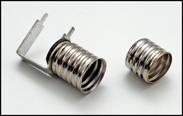
The mount and jam-nut were fabricated from brass. I would have liked to have the parts plated but this is probably not necessary if the battery is removed when the photometer is not in use thus avoiding corrosion due to battery leakage. The assembled lamp and mount are shown below.
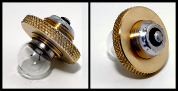
Note that the threaded socket insert is soldered to the far end of the threaded bushing. Building up a fairly large solder fillet ensures that the lamp will not be driven into the photocell by the force of the contact spring located below the battery. There is only about .080 inches of clearance between the lamp envelope and the photocell. Correctly locating the lamp is imperative. The top of the envelope of the original lamp was located 0.675 inches from the top of the battery holder. The clear replacement lamp was set to this dimension and it gave exactly the same reading on the microammeter as the original frosted lamp. A tolerance of +/- 0.015 inches is probably appropriate. The original lamp has an overall length of 0.815 inches whereas the replacement lamp measured 0.919 inches. There is a locating pin that protrudes into the battery holder that limits the possible upward movement of the battery should the lamp be forced upward out of its holder. It would be prudent to increase the length of the pin by 0.068 inches to avoid any catastrophic failure. In any event it is a prudent policy to remove the battery after each use to minimize the chance of corrosion or lamp collision with the photocell. Alternatively a 0.063 thick plastic washer having an outside diameter of 1.25 inches and an inside diameter of 0.50 inches will do the job.
Battery selection is important. In general the outside diameter of alkaline batteries is too large to fit in the battery holder. Standard zinc-carbon dry cells and the newer heavy duty cells with a zinc chloride electrolyte usually fit without modification. The all will leak in time.
1. www.reflectalite.com
Part # GV1225
2. www.bulbdirect.com
Part # 123
3. Kent's Tools, Tucson , AZ
4. Elliott Electronic Supply, Tucson, AZ
ADDENDUM:
The correctly adjusted lamp/lamp holder, lamp height gage and, insulating washer are shown below.
![]()
RAS 7/8/08